Response:
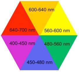
For a transition metal complex in solution exhibiting an absorption peak at 450 nm, which falls within the blue section of the visible spectrum, the corresponding (complementary) color of this solution is orange (option B).
Rationale:
The amount of UV-visible light absorbed indicates that some electromagnetic radiation successfully passes through the sample and is perceivable by the human eye. Thus, the color apparent in the visible spectrum of a complex aligns with the wavelengths of light it allows to pass rather than those it absorbs. The color that is absorbed will be complementary to the one that is transmitted.
In the accompanying image, you can view the associated wavelengths alongside their respective colors. By identifying the wavelength associated with the absorbed color, you will be able to see the complementary color that is visible or reflected.
For a transition metal complex in solution exhibiting an absorption peak at 450 nm, which falls within the blue section of the visible spectrum, the corresponding (complementary) color of this solution is orange (option B).
Materials that provide effective protection against beta particles include thin aluminum sheets, as well as low atomic mass materials like plastic, wood, water, and acrylic glass for high-energy beta-radiation. These materials can also be used in protective gear, encompassing all clothing designed to shield wearers from radiation-related harm.
Response:
n (a sin θ) = m λ₀
Since n > 1, this indicates that the fringes separate further apart
Clarification:
In a diffraction experiment, the equation for constructive interference fringes is provided by
a sin θ = m λ₀
It is presumed that the air has been evacuated from the experiment, setting n = 1
When this experiment is conducted in water, the wavelength alters
λₙ = λ₀ / n
for achieving constructive interference
a sin θ = m λₙ
we replace
a sin θ = m λ / n
n (a sin θ) = m λ₀
Given that water's refractive index is n = 1.33, the distance between the fringes increases due to n > 1, causing the fringes to move apart
Final displacement equals +24484.5 nm. The path difference observed with red light (λ1 = 656.3 nm) with 158 bright spots can be represented as: Δr = 2d2 - 2d1 = 150λ1, leading to the equation 2d2 - 2d1 = 150λ1. Dividing both sides results in: d2 - d1 = 75λ1 - - - - eq1, with d1 being the distance from the beam splitter to the fixed mirror, and d2 indicating the position of the movable mirror when 158 bright spots appear. Then, with 114 bright spots, the path difference is Δr = 2d'2 - 2d1 = 114λ1, simplifying to 2d'2 - 2d1 = 114λ1. Subsequent division gives: d'2 - d1 = 57λ1, where d'2 is the revised position of the movable mirror. The displacement of the movable mirror, (d2 - d'2), can be calculated by subtracting eq2 from eq1, leading to: d2 - d'2 = 75λ1 - 57λ2, with λ1 equal to 656.3 nm and λ2 equal to 434.0 nm. Finally, this gives d2 - d'2 = 75(656.3) - 57(434), resulting in +24484.5 nm.
The rod measures 450mm in length, while the disk has a radius of 75mm. An upward-supporting pin holds the assembly in place when Θ=0, and there exists a torsional spring with a constant of k=20N m/rad at the pin. One end of the rod connects to the pin, while the other connects to the disk.